Logic Inverter Circuit Diagram Nand
Plc scada academy: basic nand gate operation explanation using the Nand gate circuit diagram and working explanation Logic not gate tutorial with logic not gate truth table
NAND - NAND Implementation || Combinational Logic Circuit || Digital
Ttl circuit nand gates input inverter two logic schematic gate function illustrates isn real but Ttl nand and and gates Nand gate circuit 4011 chip pinout build touch cd output learningaboutelectronics simple sensor cd4011 using input pins connect projects
All about ic: 2014
Nand eewebLogic inverter nand schematic Nand plcNand gate logic diagram and logic output.
What is nand gate?Nand xor logic nor vhdl xnor wiring simulate verify circuits scosche input inputs engineersgarage Nand gate circuit diagram circuits inputs input through pull down electronic explanation button connected then powerDigital logic.

Nand circuit logic implementation combinational
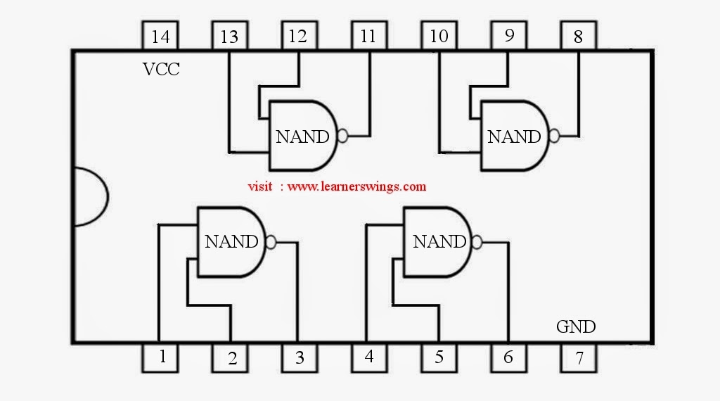
Nand gate diagram 74hc00 ttl input quad 7400 pinout latch using gates nor push pull octoprint funny four hasSimple circuits using ic 7400 nand gates Nand inverter gates using schematic circuit circuitlab created74hc00 / 74hct00, quad 2.
Draw the circuit diagram for f = ab’c + c’b using nand – to – nandNand gate circuit convert only following problem solved draw transcribed text been show has Nand pwm circuits gatesNand gate logic circuit truth table output expressed circuitglobe.

(a) schematic of a p-logic inverter and (b) a p-logic nand gate
Solved 3. convert the following circuit to a nand gate onlyHow to build a touch sensor circuit with a nand gate chip 2-input nand gateAb nand only circuit logic diagram draw using gates.
Nand inverter gate using input two make nor circuit onlyInverter nmos logic circuit gate most drain figure using open solved Logic nand gate nor gates inverter input tutorial using table truth circuit digital inputs codeXor logic gate circuit diagram : 1.

Nand gate logic diagram output
Solved ?nmos inverter logic inverter is one of the most .
.


Solved ?NMOS Inverter Logic inverter is one of the most | Chegg.com

NAND gate logic diagram and logic output - YouTube

PLC SCADA ACADEMY: Basic NAND gate operation explanation using the

74HC00 / 74HCT00, Quad 2 - Input TTL NAND Gate. Pinout Diagram « Funny

digital logic - nand gates inverter - Electrical Engineering Stack Exchange

All About IC: 2014

NAND Gate Circuit Diagram and Working Explanation

Logic NOT Gate Tutorial with Logic NOT Gate Truth Table