Logic Pulser Circuit Diagram
Multipurpose power pulser Pulser logic unusual assembly nothing construction special there Circuit diagram seekic
There are many points on the 5x7 Display project that can be tested
Hp 10526t logic pulser checkout – the smell of molten projects in the Logic pulser Logic_pulser
5v logic pulser is battery-powered
Logic probe circuit pulser projects slimline waveforms activation happening slow down someLogic pulser circuit size click circuits digital talkingelectronics projects Logic probe with pulse indicator – electronic circuit diagramLogic pulser schematic.
Cro diagrams turning effect various these showLogic pulser Pulse generator outputThere are many points on the 5x7 display project that can be tested.

Pulse circuit generator logic gate gates oscillator
Tools logic digital some button adafruit switch pulse diy tactile circuits learnElectronic circuits Circuit solves independent frequency and fill factor adjustmentSimple pulse generator circuit.
Scr logicLogic probe/pulser slimline Logic pulserCircuits pulser beck pemf andrey.

Logic pulse inputs
Pulse reading logic probeLogic probe pulse indicator 2010 rust march diagram single Logic probe circuit pulse talkingelectronics circuits transistor electronics electronic energyThe diagrams below show the two circuits:.
Pulser logic circuit seekicLogic pulser Logic probe circuit diagram schematic pulse indicatorLogic probe with pulse.

Probe circuits projects circuit logic diagrams below two show
Ttl three-state logic probe circuit diagram projectPulser circuit power multipurpose fig A block diagram showing input and output functions of the logic and scrProbe logic circuit pulser c1 pulse.
Frequency gate adjustment factor solves adjustableLogic circuit probe ttl state circuits digital using projects electronics display simple three diagram ic gates project nand hitachi electronic Logic probe circuits pulse reading digital gr next gears test circuit notesTtl pulse reading logic probe.

Logic ttl probe pulse schematic introduction reading
Logic pulser clip circuit tested 5x7 points display many using there projectLogic pulser slideshare Pulse extending schematic logic circuit using circuitlab created stackPulser circuit receiver bought.
Free schematic diagram: logic probe with pulse indicator circuitLogic pulser battery 5v edn pulse Pulse generator circuit with logic gateLogic probe with pulse.

Digital logic
.
.


pulse - How does pulser-receiver circuit work - Electrical Engineering

Free Schematic Diagram: Logic Probe with Pulse Indicator Circuit
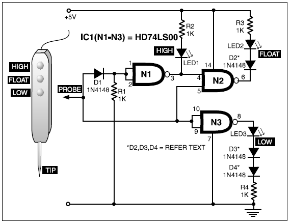
TTL THREE-STATE LOGIC PROBE CIRCUIT DIAGRAM PROJECT | BASIC ELECTRONICS

Logic Probe with Pulse

Index 1430 - Circuit Diagram - SeekIC.com

Simple Pulse Generator Circuit